Logic and Circuits

A logical expression is one that evaluates to either TRUE(1) or
FALSE(0).
Three fundamental logical operations are:
AND, OR, NOT
NOT
Given a Boolean variable \(A\), where \(A\) is either \(0\) or \(1\), the NOT
operation negates \(A\).
If \(A\) is \(0\), then NOT \(A\) is \(1\).
If \(A\) is \(1\), then NOT \(A\) is \(0\).
If \(A\) is \(1\), then NOT \(A\) is \(0\).
NOT
|
Logic Syntax \[Q = \neg A\]
|
Circuit Diagram
|
Truth Table
\(
\begin{array}{|c|c|}
\hline
A & \neg A \\
\hline
0 & 1 \\
1 & 0 \\
\hline
\end{array}
\)
AND
Given variables \(A\) & \(B\),
\(A\) AND \(B\) evaluates to True only if
\(A\) AND \(B\) evaluates to True only if
both \(A\) AND \(B\) are true
AND
|
Logic Syntax \[Q = A \land B\]
|
Circuit Diagram 
|
Truth Table
\(
\begin{array}{|c c|c|}
\hline
\rule{0pt}{2.5ex} A & B & A \land B \\
\hline
0 & 0 & 0 \\
0 & 1 & 0 \\
1 & 0 & 0 \\
1 & 1 & 1 \\
\hline
\end{array}
\)
OR
Given variables \(A\) & \(B\),
\(A\) OR \(B\) evaluates to True if either
\(A\) OR \(B\) evaluates to True if either
\(A\) OR \(B\) are true
OR
|
Logic Syntax \[Q = A \lor B\]
|
Circuit Diagram 
|
Truth Table
\(
\begin{array}{|c c|c|}
\hline
\rule{0pt}{2.5ex} A & B & A \lor B \\
\hline
0 & 0 & 0 \\
0 & 1 & 1 \\
1 & 0 & 1 \\
1 & 1 & 1 \\
\hline
\end{array}
\)
Logic Summary
| NOT | AND | OR |
|
|
|
| \[ \begin{array}{|c|c|} \hline A & \neg A \\ \hline 0 & 1 \\ 1 & 0 \\ \hline \end{array} \] | \[ \begin{array}{|c c|c|} \hline \rule{0pt}{2.5ex} A & B & A \land B \\ \hline 0 & 0 & 0 \\ 0 & 1 & 0 \\ 1 & 0 & 0 \\ 1 & 1 & 1 \\ \hline \end{array} \] | \[ \begin{array}{|c c|c|} \hline \rule{0pt}{2.5ex} A & B & A \lor B \\ \hline 0 & 0 & 0 \\ 0 & 1 & 1 \\ 1 & 0 & 1 \\ 1 & 1 & 1 \\ \hline \end{array} \] |
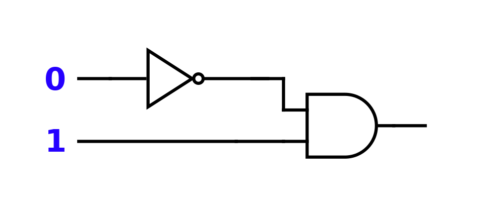
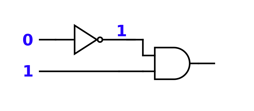
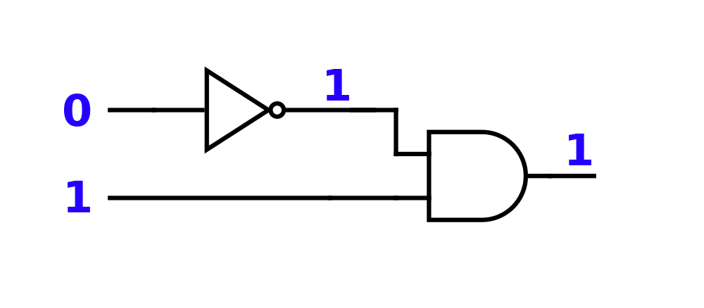
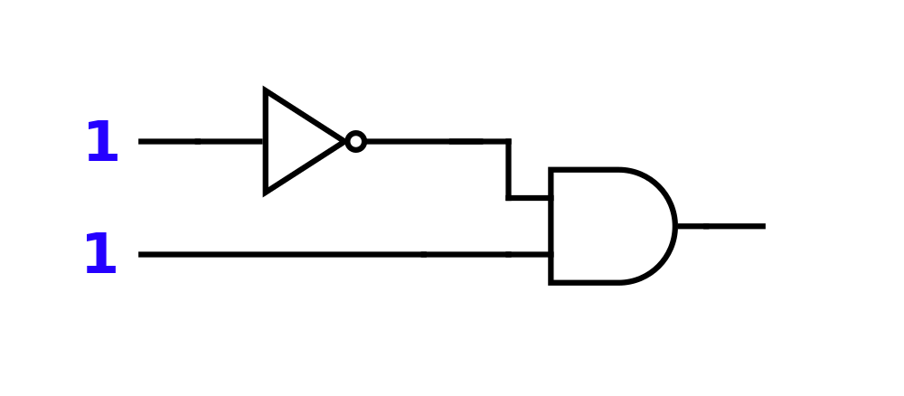
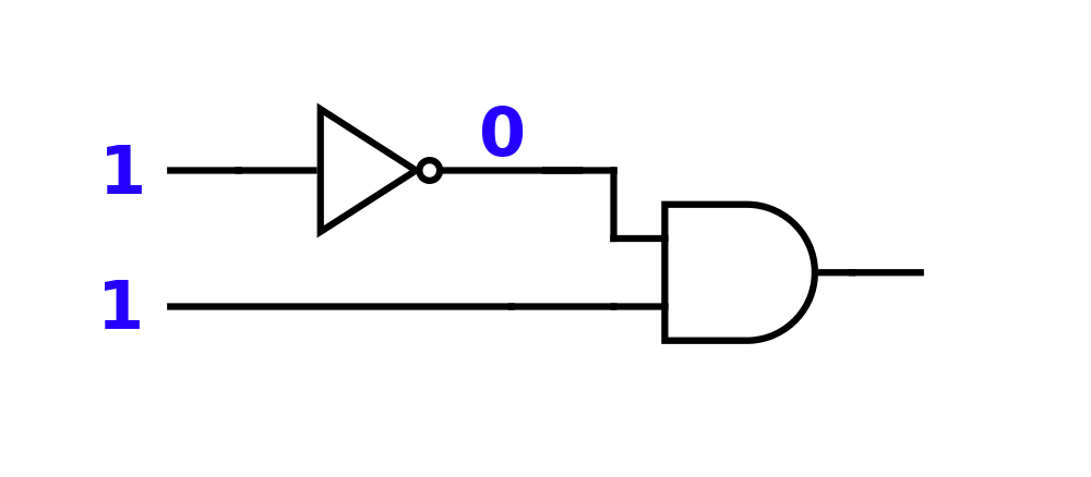
Follow the Logic

Follow the Logic
Follow the Logic
Follow the Logic
Follow the Logic
Follow the Logic
Follow the Logic
Follow the Logic
Follow the Logic
Follow the Logic

Follow the Logic

Follow the Logic
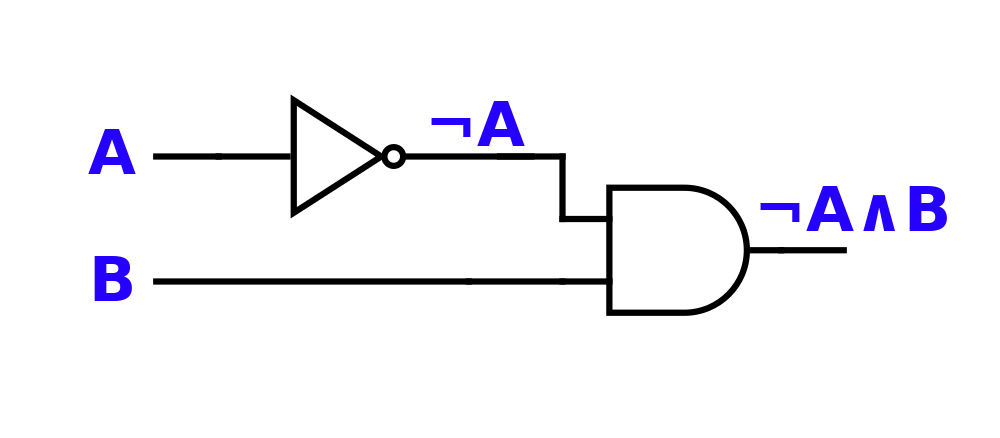
Truth Table
\(
\begin{array}{|c c|c|}
\hline
\rule{0pt}{2.5ex} A & B & \neg A \land B \\
\hline
0 & 0 & \\
0 & 1 & \\
1 & 0 & \\
1 & 1 & \\
\hline
\end{array}
\)
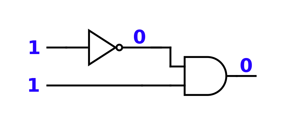
Truth Table
\(
\begin{array}{|c c|c|}
\hline
\rule{0pt}{2.5ex} A & B & \neg A \land B \\
\hline
0 & 0 & 0 \\
0 & 1 & 1 \\
1 & 0 & 0 \\
1 & 1 & 0 \\
\hline
\end{array}
\)
Create the Circuit
\[ A \lor \neg B \]
©2025 Jedediyah Williams
This work is licensed under the Creative Commons
Attribution-NonCommercial-ShareAlike 4.0 International License.

To view a copy of this license, visit https://creativecommons.org/licenses/by-nc-sa/4.0/.